Design principles
The mechanical design of MOANA was guided by the following principles:
- Try to not reinvent the wheel: since 1668, when Newton built the first telescope now bearing his name, every variant of the design has been tried, and the solutions that have imposed themselves over 350 years of trial and error are now probably close to optimal.
- Try not to overengineer: mechanical engineering is not biology, and simplicity is a virtue. Performing the same function, the simplest design is often the most robust and reliable, and usually the simplest to build. Overengineering is often lazy and lacking vision.
- If you can buy it, don’t build it. Buying a quality part (say a mirror cell) can be expensive. But engineering and building a better one can be an order of magnitude more expensive! Each prototype needs to be build (with a cost often comparable to the final product), tested and improved. Then for the final production, machining a one off part is always much more expensive or time consuming (per unit) than machining a batch.
- Build so the telescope will outlive you.
Tube or Truss?
The first decision to make was: truss or tube? One way to answer this question is to review the existing commercial instruments in the category considered. For an f/4.5 10″ newtonian, we find many tubes (ASA, ONTC) and very few truss (AstroTech). This quick surveys through a telescope catalog seems to indicated instruments with a diameter at or smaller than 10 inches are mostly tubes, while instruments with a diameter larger than 14 inches are mostly truss.
Another way to answer the question is to use physics. Let’s look at the formula for the “second moment of area” of a tube. It informs us on the stiffness of the tube in cantilever applications. It can be calculated as follows:
I=E π / 64 (De4 – Di4) with De exterior diameter and Di interior diameter of the tube. I is the second moment of area and E the extensional modulus and π is Pi.
We can substitute the external diameter with the wall thickness w, using: De= Di +w. It then becomes apparent that the tube rigidity increases as the power 3 of the tube diameter and the power 4 of the wall thickness.
Those considerations should convince you well built large tubes offer an incredible rigidity. Further tubes are mechanically simple, and can be rotated if supported by rings.
The advantages of the truss are:
- access inside the telescope is much more easy than inside a tube, which can be essential for the collimation (Richey-Chretien, Corrected Dall-Kirkham),
- formulas like a serrurier truss may deform while maintaining collimation,
- can be disassembled,
- for big structures, lighter and easier to manufacture than a tube.
For MOANA, access through the tube for collimation is not required (newtonian) and the overall size makes tube a possible option. So due to the rigidity and simplicity consideration exposed above, this is what I chose.
Tube
I did not consider legacy materials (sonotubes), steel (has to be too thin to be light) or exotic materials I could not source (Astro Physics for example offers a tube made of an exotic alloy probably similar to Invar, with near zero thermal expansion).
I considered 2 types of material for the tube: aluminum and composite. I had made one comparable instrument in the past out of an aluminum tube, sourced from Parallax Instrument. I found the tube heavy, very susceptible to thermal expansion (altering the length of the tube, hence the focus while temperature drops with the night), and all the aluminum tubes I have come across (from Parallax or other sources ) were slightly deformed. Bending those tubes back into shape is an uphill battle. So, I decided to go for a composite tube considering the low weight, low thermal expansion, high rigidity and the absence of plastic deformation (the tube would arrive to me with its original shape -or cracked, but not bent). The drawback of composite, versus aluminum, are: high price and low machinability (you can for example tap an aluminum tube, while a carbon tube would require an insert).
If I was going the composite way, I figured I may also go all the way and use Carbone fiber (due to its rigidity) over other composite types, like fiber glass.
From there I considered 4 suppliers:
I hesitated between a solid wall and a honey combed wall tube. I ended up with a solid wall tube: less expensive, more resistant to dings, easier to make holes without compromising the structure and sufficiently rigid for the task. Maybe going for a honey comb tube would have save a few grams, added some rigidity and be more glorious…
I ended up with the following solid wall tube, from Carbone Scope tube:
- Inside Diameter: ID=12.61″
- Outside Diameter: OD=12.88″
- wall thickness=0.135″. This correspond to the thickest wall available from this manufacturer
- tube length 50″
- focuser hole center at 40″ of one extremity and 10″ of the other.
- Clearcoat finish exterior, flat black interior.
- focuser hole diameter: it is a Starlight 2″ focuser with OD of 2.54″, so the focuser hole needs to be between 2.6″ and 2.75″ diameter.
Tube Ring
Three options there: find and buy a commercial ring corresponding exactly to your tube specifications, manufacture your own ring, or get a set from Parallax instrument. Joe at Parallax makes rings for scopes from 3 to 26 inches of diameters, fine stepping with many intermediate sizes. Because the rings are made of molded aluminum which is quite thick, intermediate sizes can be achieved by grinding the inside of a ring of the closest inferior size. For example, for my 12.88″ OD tube, a 12.7″ standard size ring was enlarged, grinding the interior, removing 0.09″ (2mm) everywhere in the inside of the ring. Molded aluminum is quite soft compared to the 6061 aluminum used for other parts of the scope, and the grinding process is quick and easy.
My opinion now: if one is used to the tolerance of CNC machining, molding is quite crude, and I had to rework the rings quite a bit to make them work. In particular the hinges were both out of tolerance and I had to grind the rings along the hinges to insure no part would scratch the tube in the pivot movement consecutive to opening the ring. I also had six 1/4-20 holes taped by Joe into each ring to fixate the dove tails, and 2 of the holes were out of tolerance (not positioned to spec on the ring). The ring are also quite heavy, and painted (rather than anodized). With some effort, everything worked, and I now have a solid system. However, at some point I plan to design parametric rings, and have that CNC machined and anodized to replace the current solution.
Primary collimation cell
Teleskop-Express in Germany and Aurora Precision in Washington state have high quality collimation cells. Building, testing, and iterating to get a product comparable to or better than the Aurora AZ cell would certainly be very time consuming and expensive. Although I may end up going down that route and make my own Carbone fiber collimation cell some day, for now I am using one of Aurora Precision AZ cell. The cell is in aluminum, the collimation screws are standard 1/4-20 screws. The design is of the “floating” type, with the mirror cell floating on springs. The golden knobs are used to collimate (pull) and the red knobs are used to lock the cell (push).

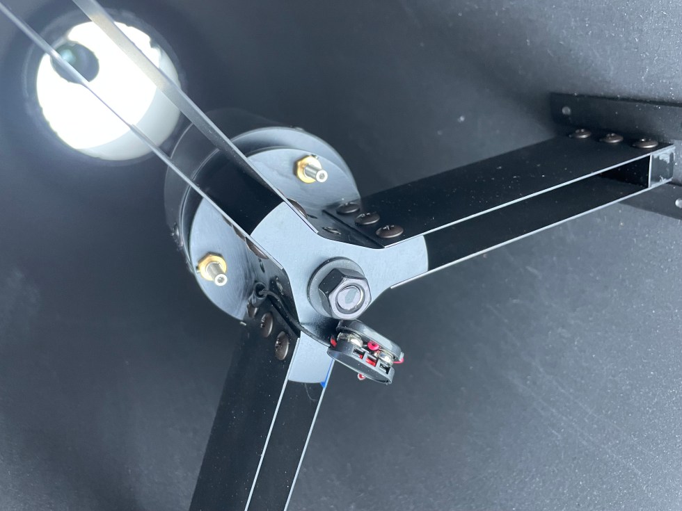
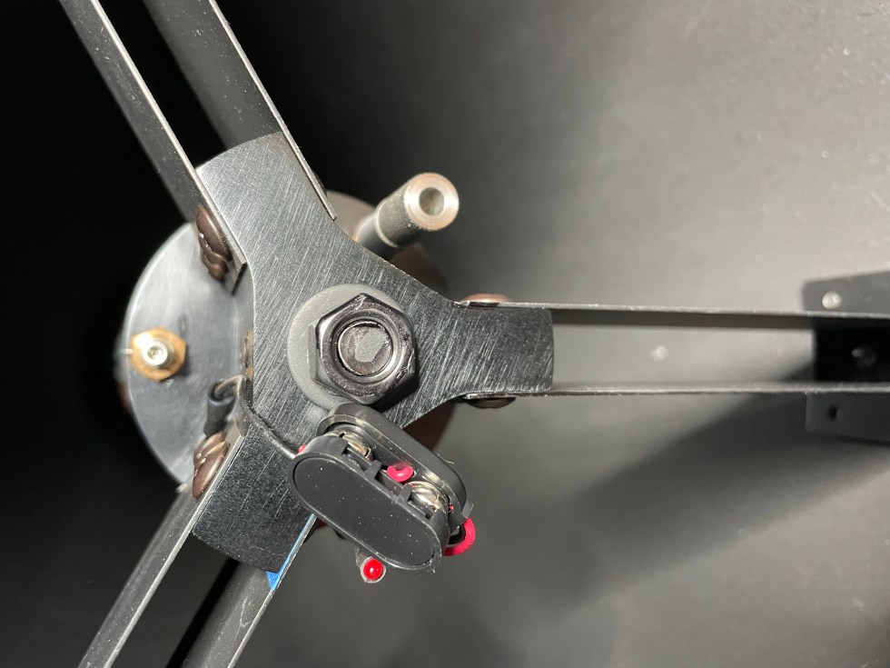
Secondary assembly
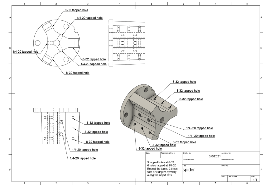
On this front I was unable to find any commercial solution sturdy enough for my need, so I designed my own. I wanted a system that would be extremely rigid, precisely made of CNC machined aluminum, with micrometric screws (rather than standard screws), fully adjustable, mechanically insulated from the carbon tube to tolerate differential thermal expansion, and with a 120 degree symmetry for easier collimation with 3 sets of screw. And with 12v supplied through the vanes. This is a very stable and sturdy system, which has performed flawlessly, and give Moana its signature diffraction patter. Many hours of engineering, CAD design and prototyping were invested here, and this system has a potential to interest other ATM.


Focuser
The focuser is a Feather Touch® FTF2015BCR Rotatable 2.0″ with a BA20FL Flat Base 2.0″ screwed on a custom made CNC curved adapter. This allows very precise collimation of the focuser. The outside diameter of the Feather Touch 2” focusers is 2.54” so the opening ofthe telescope tube needs to be bored between 2.54” and 2.75”.


Corrector assembly
I use a Televue Paracorr, with its M54 adapter (Televue M54-1073, from the Paracorr 2.4″ to standard male 54), then an SXF54A female M54 adapter to my SFX Midi filter wheel.

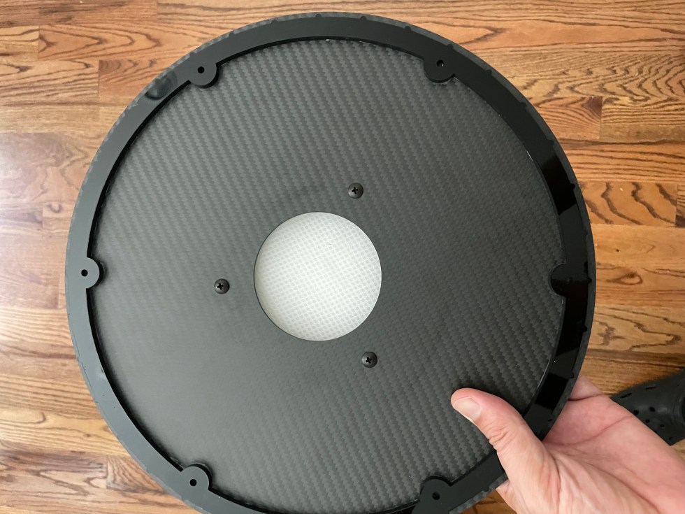
The back of the telescope is a ring of flat fiber carbon, with a screw top filter box 3D printed in black PetG. The CAD files are distributed as well.

The parts cad models and drawings can be downloaded from the link below. The step files are what will be used by the machinist to program the CNC. The parts with taped holes have additional drawing defining the taps.